
Welcome to the LGT8 project
PRIMARY INFORMATION ABOUT IT
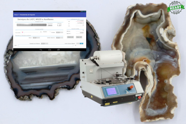
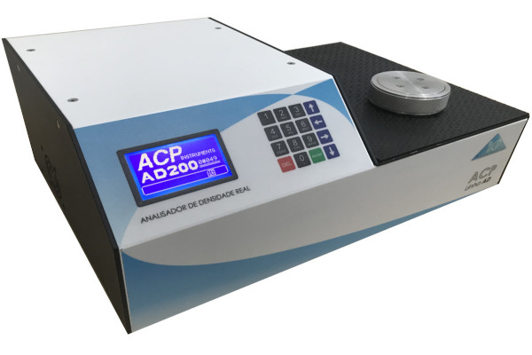
This project was requested by ACP Instruments Ltda. and Acil Weber Equipamentos Científicos Ltda. at the first quarter of 2013 in order to meet the needs of its client (CIA Vale do Rio Doce) regarding the modernization of one of its instruments in operation in the laboratory. The instrument in question (precision polisher for geological samples from Logitech UK) was dawn due to lack of replacement material (declared obsolescence). In order to recover its functioning, the following goals were established:
- Replacement of all control electronics by microprocessor systems.
- Review of all mechanics, repair of fairings and accessories.
- Creation of a modern user interface via tablets/android.
- Implementation of the possibility of manual operations if desired.
- Increased accuracy (50%) of the concavity measurement on the roughing table.
- Provide the user with tools for creating more complex methods via a graphical interface.
- Provide possibility for the system to autonomously (via machine learning) estimate a better strategy for roughing and polishing.
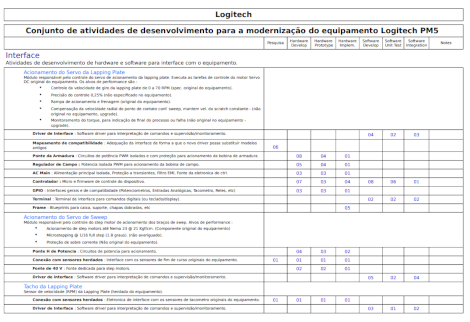
As a primary support to the sales team and production teams, a simple guidance draft and a worksheet estimating man-hours per development unit were sent to the contracting party in order to guide the construction of the commercial proposal to the final customer and the project was approved. These documents can be accessed at Men/Hour Map - LGT8 Project e Primary Report - LGT8 Project
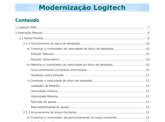
The operations manual released after the installation & tests at the final customer site may be found at LGT8 User Guide (Brazilian Portuguese version)
Once the goals were established, the research phase to build the knowledge base and the reverse engineering of the legacy systems were carried out in order to support the construction of the architecture of the new system. The theoretical research on the physical processes inherent to the operation of the instrument can be accessed at LGT8 Lap&Polishin Theory
NOTE: Despite the fact that the codes, circuits and machining plans registered in the project repositories can effectively produce fully functional
prototypes, such references
System Overview
PRIMARY ARCHITECTURE / MODULES
The preliminary specifications above led to the division of the project into 3 main areas of activity. Such areas are distinct in applied technology but inter-dependent. The figure below illustrates an overview of the system and a primary breakdown can be found in the corresponding sections of the document Project Sections on MHMap (Brazilian Portuguese)
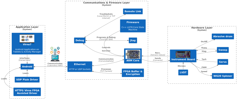
The areas depicted above may be best understood by following :
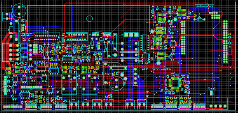
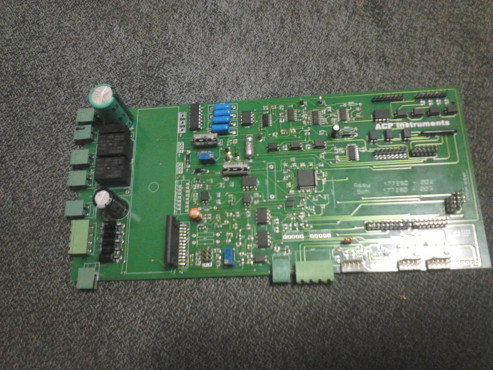
- Hardware Tier : Responsible for the direct interface with sensors and servo actuators in the instrument. It is composed of PCBs populated with interface electronic circuits. Details at Hardware Layer
- Firmware Tier : Responsible for the direct control of the instrument's systems using a system composed of a state machine, A/D conversion routines & sensor calibration, actuation of servo controls and communication handling routines via TCP/IP. Details in: Firmware Layer
- User Interface Tier : Responsible for communicating with the user and implementing high-level routines in the instrument's control strategies (editing working methods and autonomous estimators) Details on : Application Layer
- Documentation and Production Support: User manuals, function test routines, performance analysis. Details in: Support Material
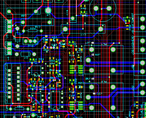
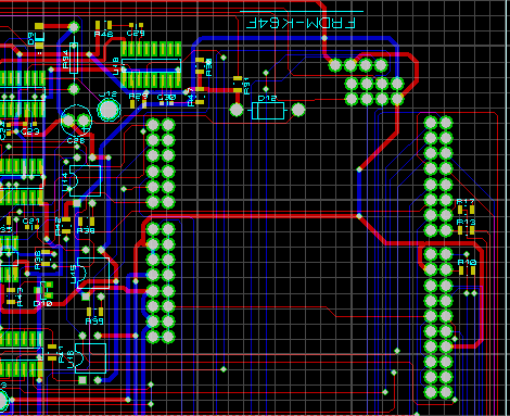
Hardware Layer
INTERFACE WITH INSTRUMENT
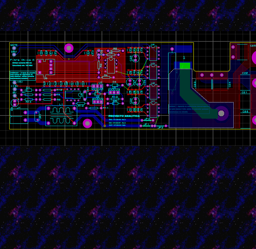
The various sub-systems composing the interface with the sensors, servos and actuators as long as the tools used to design the parts and circuits are listed below. Please use the icons and at the right to navigate to the desired section.
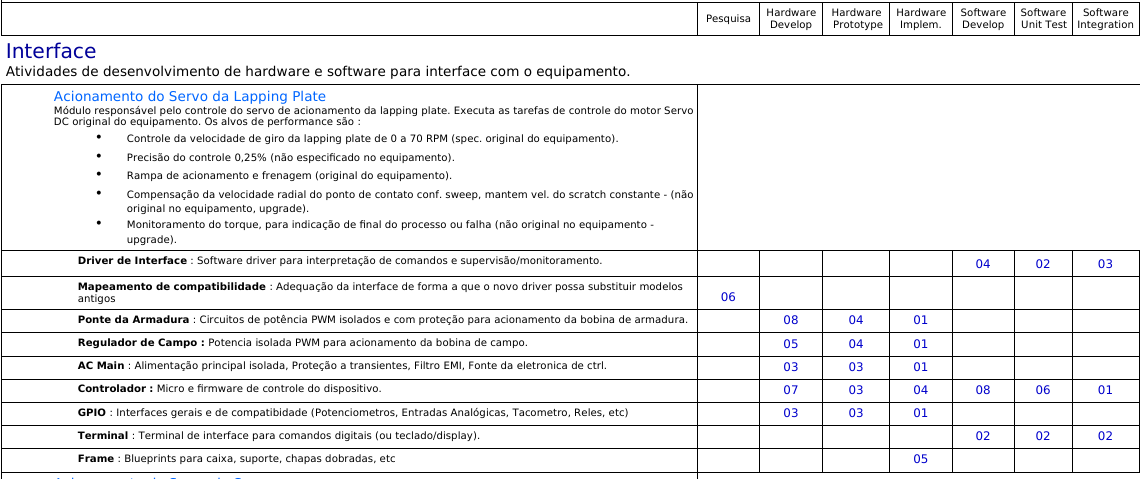
Module responsible for controlling the lapping plate drive servo. Performs Servo motor control tasks over the original equipment DC servo motor (80V - 60 Kgf). The performance targets are:
- Lapping plate rotation speed control from 6 to 70 RPM (original equipment specification).
- Control accuracy 0.25% (not specified on equipment).
- Compensation of the radial velocity of the contact point relative to the acc. sweep to maintain sample speed constant upgrade
- Torque monitoring, to indicate the end of the process or failure (not original to the equipment) upgrade
The circuit drawing (in pdf format) of this sub system may be found at the repository Servo Sub System
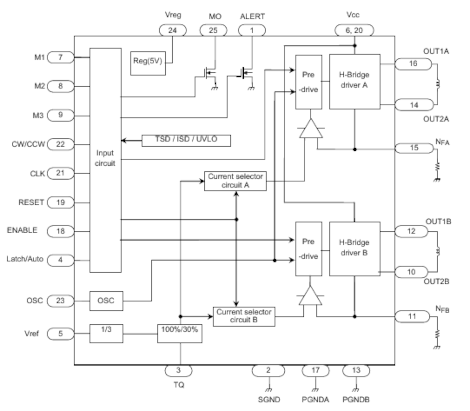
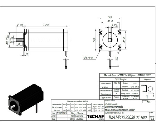
Mechanical driver of the sweep arm(s). It positions the sample driving arm according to calculation algorithms based on the velocity and flatness conditions of the lapping plate. Fulfill the following tasks:
- Provides precise sample placement according to Flatness control state machine commands (for Plate reshape - conc/flat/vex)
- Also according to the user's manual command (Via UI -> Analytics or instrument panel) upgrade
- Coordinates with the Servo module the calculate to set the correct sample relative velocity with the lapping surface upgrade
- Informs radial position for Plate SM (const. speed removal) upgrade
- Calculates and stores drive startup and calibration parameters. (end-of-stroke steps and step/milli-radian)
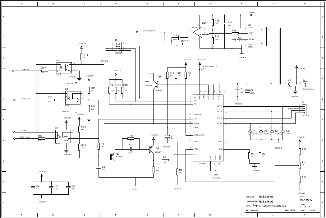
- Step Motor driver to a Nema 23 21 Kgf/cm @ 1/16 full step (1.8 degree) plus the associated 40VDC power supply
- Over current detection & torque modulation upgrade
The circuit drawing (in pdf format) of this sub system may be found at the repository Sample Sweep Sub System
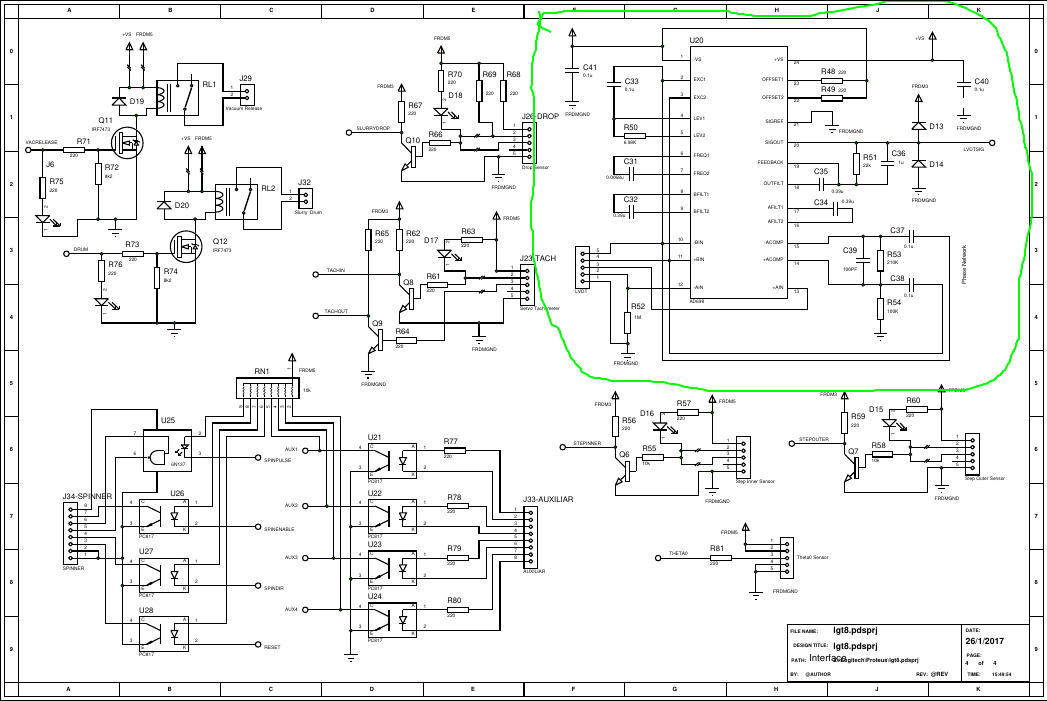
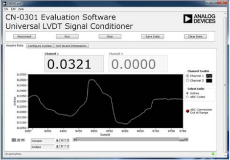
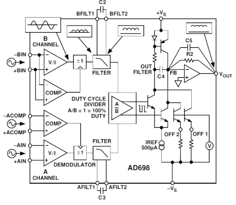
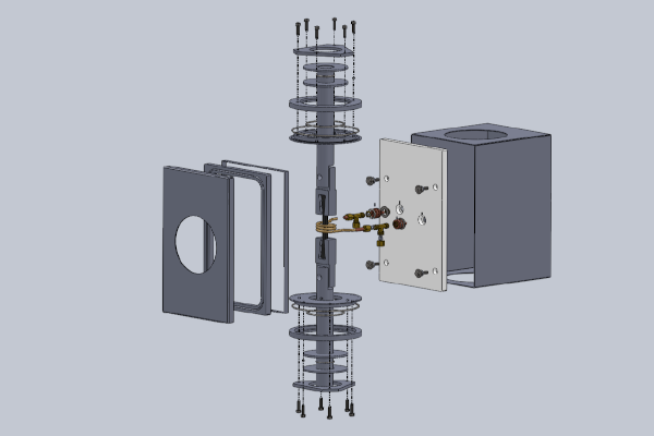
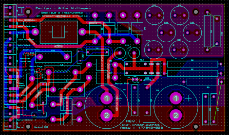
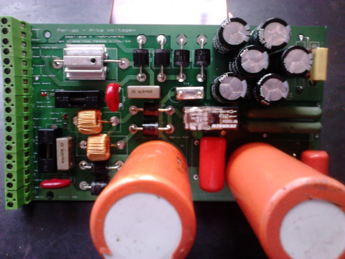
Module responsible for the interface with the instrument's legacy LVDT transducer. The design utilizes the Analog Devices AD698AH device for both excitation and signal capture tasks.
- For the design of the correct interface with the device, a reverse engineering phase of the instrument's original probe was carried out and a theoretical research on possibilities of improving the system's performance was carried out.
- Due to his ratiometric architecture, the Analog Devices AD698 was used with excitation of 10V rms @ 2.5Khz (200 ppm/°C). Reading for coils in series resulted in 2.2 mV/V per mill (100 ppm/°C)
- The signal was sent in unbalanced mode for 16-bit A/D conversion.
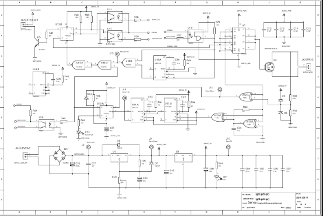
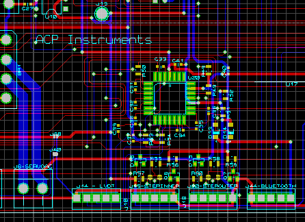
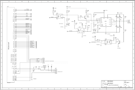
The circuit drawing (in pdf format) of this sub system may be found at the repository LVDT Monitor Sub System (at the upper right corner)
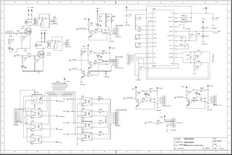
Several sub systems may be listed under this category,below are some of them
- Tachometer interface to measure speed (primary function of the original instrument) and angular position of the lapping plate (used in coordination with the sweep module to identify plate areas during flatness corrections) upgrade
- Optical sensors to indentify start an end position of the sweep arm
- Controler to drive the spinner (WG20 Device) via DC/H-Bridge
- Relays to activate Drum, Vacuum pump, and other devices
The circuit drawing (in pdf format) of this sub system may be found at the repository GPIO Sub System and ARM Core Sub System
Application Layer
THE USER INTERFACE AND ANALYTICAL PROCEDURES
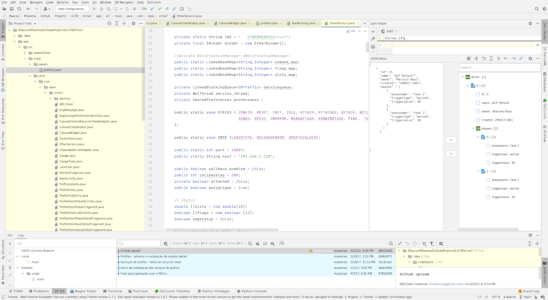
The User Interface of the instrument. The base code is at Virna 7 Repository. Bellow are some of the modules developed, please use the icons and at the right to navigate to the desired section.
The activities below provide the instrument's operational base services, as well as the tools for editing test strategy methods and algorithms.
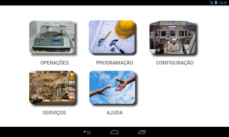
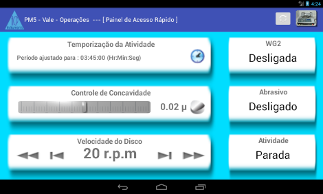
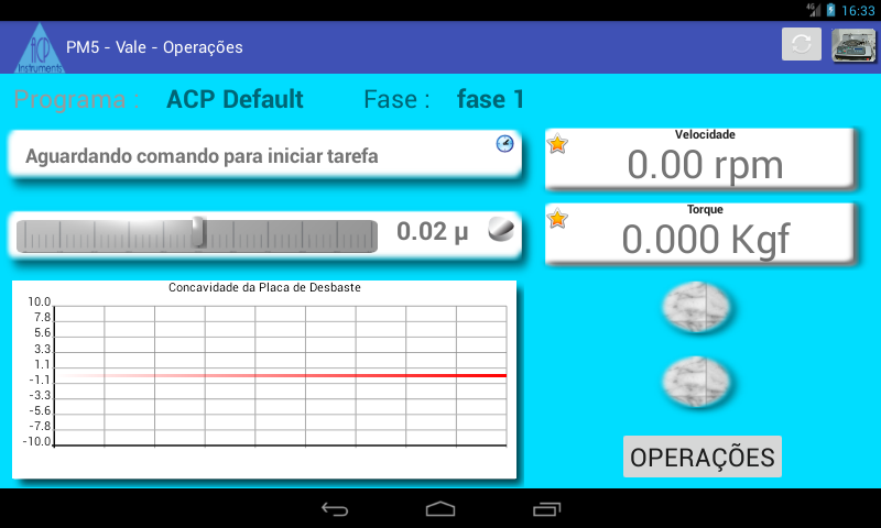
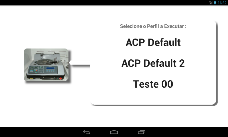
- Common Operations : This activity provides a simplified and objective man-machine interface. It focuses on the use of pre-configured and quick interpretation instrument status indicators as well as immediate action actuators or a maximum of 2 levels. Code segments may be browsed at RunActivity.java (State Machine at line 988) and Gauge.java for example.
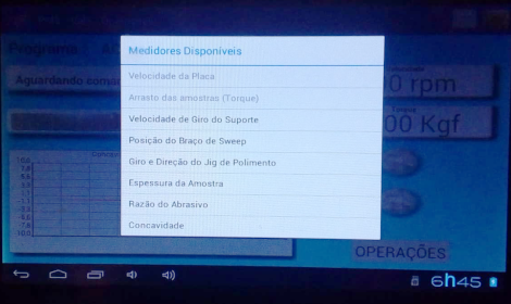
- Advanced Operations: This activity provides a more elaborate man-machine interface, fully configurable and with better graphic resources in order to provide more freedom in choosing and detailing the instrument's various sensors. A graph of historical flatness control strategy results is also provided. The codes at RunTaskRightGauges.java and GaugeType.java are examples of the structure
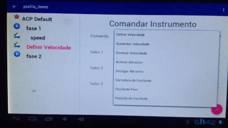
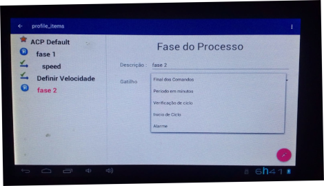
- Method Edition: Like any analytical instrument, the advanced operations can (and should) be pre-configured by the researcher in the form of methods. This activity provides tools and graphic edition for the construction of scripts composed by the sequence of actions. Some code at ProfileManager.java and ProfilePhase.java for example.
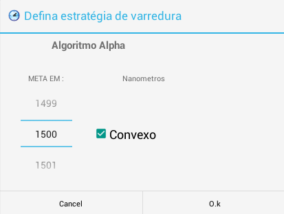
- Strategy Algorithm Selection: In order to increase the quality of the control and provide greater ease in configuring the flatness control strategies of the lapping table, the possibility of loading up to four algorithms in the instrument's control state machine was implemented. codes in SetSweepDialogFragment.java and Support3.java
In this section, we find the modules responsible for the general administration of the application and the support services for its operation.
- A replacement module for the original Android activity manager with a clean version focused on analytical tasks. It also removes unnecessary android services from the analytical environment. Some code at RunActivity.java and Canvas_Coordinator.java
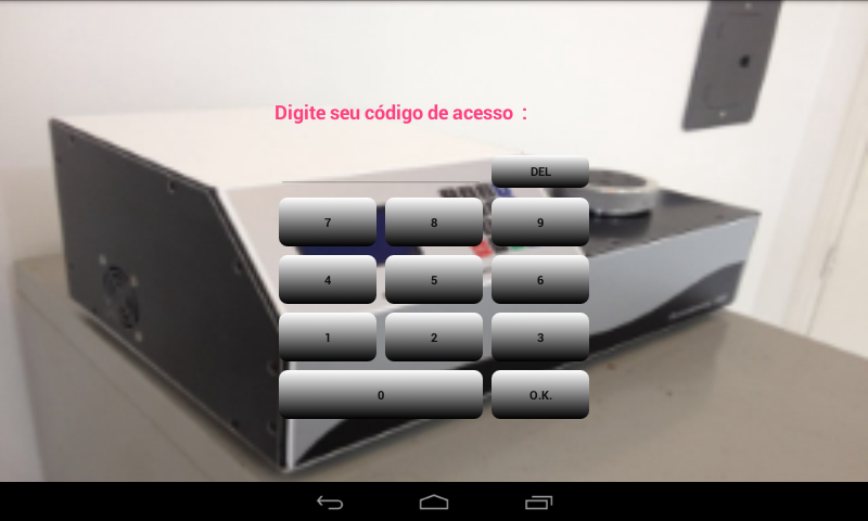
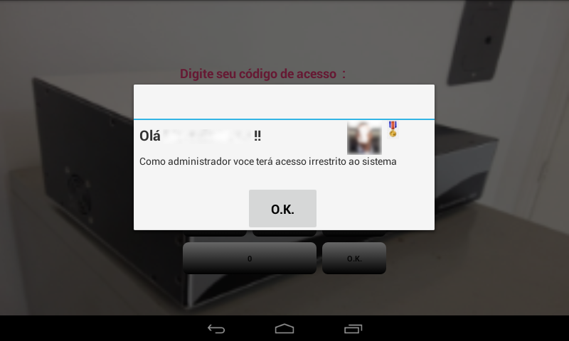
- A module for user authentication and privilege control services, initial login screen and blocking services due to inactivity. See UserDialogFragment.java and some user management code at SettingsActivity.java
- Some of the miscellaneous general configuration services may be browsed at e.g. Support3.java and Virna7.java
- Some of the code used on the mechanisms to provide the event bus and the post office services to the various activities of the application may be browsed at AcpMessage.java and SMTraffic.java for messaging payloads and sections on RunActivity.java for e.g. Context Management, USB&Ether hooks, Event Callbacks ...
Several services to support the system operation (communications, timers, event bar, message brokers)
- Communication services module via TCP/IP packets. It uses UDP sockets and its own recovery mechanisms to ensure a better balance between low latency and secure operation. Most of the code to perform this task may be found at EtherService.java and the his interface with the internal activities event bus and post office services (AcpMessage & SMTraffic state machine thread)
- Drivers in the Linux kernel environment in C and C++ tweaked to help provide low latency and automatic recovery of the Ethernet Gate service in the Android environment (which does not provide sufficient packet transit performance for real-time operations). The code to the kernel driver may be found at C/C++ PHY Ethernet Kernel Driver to Android 21
- Interface with the HTTP server of the LGT8 machine firmware. Designed to overcome access restrictions on non-standard ports by firewalls in lab networks. Uses headers and simplified segmentation (and version assisted by a packet buffer implemented in FPGA) so as to not compromise high priority firmware operations (A/D conversion and Servo PWM). Code in C and RTL may be found at fpga_packet_buffer/virna7.c
Such activities provide the necessary services for the general maintenance and calibration of the instrument's sensors and the configuration/monitoring of the communication protocols between the various operational modules of the system.
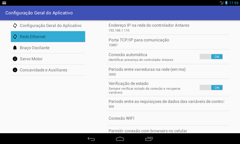
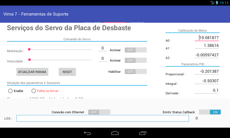
- Servo Maintenance Services: Servo driver configuration tools from Lapping table - Provides direct servo command, DC motor calibration curve, modulation period and PID controller parameters (to the C++ driver at the firmware) for acceleration and damping. Works together with the Sweep driver to control the constant speed of sample sweeping in Beta and Gamma algorithms. code in ServoFragment.java
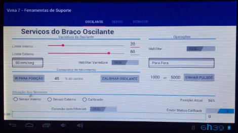
- Sweep Maintenance Services: Sample Holder Swing Arm Setup Tools. It provides tools for the direct command of the arm, calibration of the limit sensors of full course and the amplitude of the useful space for information of the algorithms alpha and beta (control of the relative velocity of the sample). code in SweepFragment.java
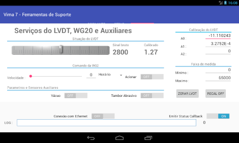
- LVDT Maintenance Services: Provides direct access to the Lapping table's concavity monitoring LVDT sensor as well as its calibration parameters. It works together with the servo module in mapping the table to provide information to the strategy algorithms. It also provides access to the sample holder WG20 spinner and auxiliar services (abrasive drum and vacuum pump control) code in MonitorFragment.java
- Packet Log Monitoring Services: Ethernet packet log monitoring services. Code in EtherService.java
C/C++ Firmware Layer
THE C++ CORE & STATE MACHINES CONTROLLING THE SILICON
The C++ code (state machines / TCP/IP comms protocol digest / bussines & housekeeping) and the C pure code (hardware drivers, ARM CMSIS interface / temporization & real time event handling) that compose the close control of the instrument. The code architecture favors objectivity (KISS) and reliability (Return on Completion State Design & Watch Dog Monitoring), reserving the operation strategy calculation to the associated application helped by a real-time communication channel. Please use the icons and at the right to navigate to the desired section.
These are some of the general housekeeping services. The code of this module may be browsed at the repository Main services
- Real Time services: Such services basically comprise administration tasks and context switching via high priority interrupt handlers for PWM, A/D Conversion, Tachometer and reference clock resources for state machines. See BOARD_TACH_IRQ_HANDLER, installADCHandler, installTickHandler, PIT_SLOWTICK_HANDLER in LGT8 Main.cpp
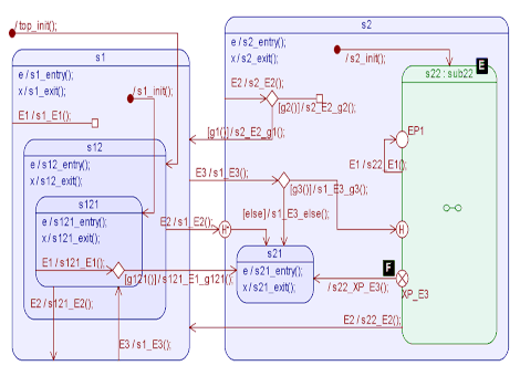
- State machine tick: The mapping structures and timing of state machines used in device services can be found at antares.h and statemap.h for example.
- Log and PUB/SUB Services: The provision of communication services and triggering events between the various state machines is performed by a simple post office structure (publish/subscribe) in LGT8 Main.cpp #314. The log/trace service for debugging can be found in LGT8 Main.cpp #237. The ACPMessage structure is at in antares.h.
Below are some of the High and Low Priority services to the machine resources. The code of this module may be browsed at the repository Controller Code Base
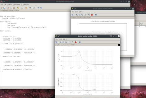
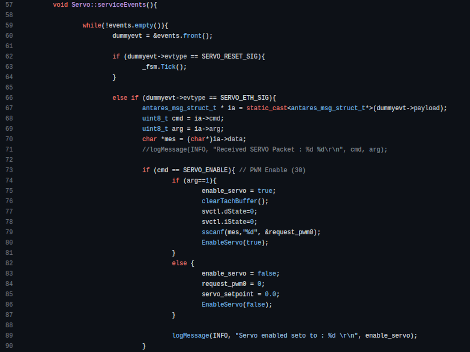
- Servo Services: This module contains the control state machine for the servo motor that drives the polishing plate. It is composed of a PWM modulator that uses dedicated timers from the ARM M4 core of the CPU and a PID controller for acceleration and damping control. Receives the commands and configuration from the application's strategy modules. Codes in Servo State Machine and board.c #199 and
- Sweep Services: This module contains the state machine for controlling the Step Motor for driving the oscillating arm of the sample holder. It comprises a simple core for capturing end-of-stroke sensors for calibrating the mapping of the angular position of the arm. Receives commands and configuration (sweep speed, damping) from the application's strategy modules. Codes in Sweep State Machine
- LVDT Monitor Services: This module contains the services of the interrupt processing routine for the LVDT sensor signal of the monitoring probe. This probe is used for the polishing plate concavity control routines. It provides a 16-bit A/D conversion and applies FIR integration / filtering in order to minimize the noise induced by the servo drive. It then transfers signal to the strategy routines in the application via ACPMessage protocol using UDP drivers. Codes in Monitor Services and LGT8 Main.cpp #167
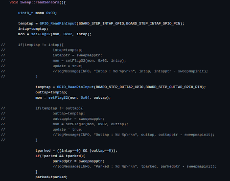
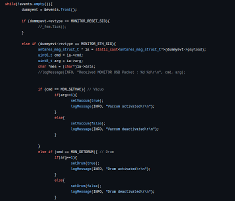
- Low Priority Services: This module contains the general services for triggering and monitoring various instrument sensors (Vacuum, Abrasive Drum, WG20 Sample Spinner) as well as the M4 core port configuration (GPIO & Clock setup). codes in Monitor Services and board.cpp
The code of this module may be browsed at the repository Modified TCP/IP Stack
- TCP/IP UPD Link: These are the services used to communicate with the user interface application. It uses a legacy TCP/IP stack (LWIP) and modified to provide real-time traffic via the use of UDP packets with a fixed (and fast) messaging protocol and recovery routines coordinated with the Android's device driver on the application side. Some codes in udp.c and LGT8 Main.cpp #387
- HTTP Server: In order to provide greater flexibility in operation (possibility of operating the instrument via a web browser) and the use of networks where there are restrictions (firewalls) on the use of non-standard ports in the TCP-IP protocol, a simple HTTP page server was implemented . Codes can be seen at httpd.c and httpd_structs.c The FPGA assisted packetbuffer code version (proof of concept version) may be browsed at the fpga_packet_buffer
Production Support and Tools
HELP/LIBRARIES API DOCS. & TOOLS USED
Please find bellow some references and documentation of the project
- The operations manual released after the installation & tests at the final customer site may be found at LGT8 User Guide (Brazilian Portuguese version)